Why freeform surfaces from Rhino are so difficult to use in traditional CAD systems
In modern product development — particularly in industries like consumer electronics, medical devices, and automotive interiors — aesthetics and ergonomics often demand freeform surfaces. Rhino (Rhinoceros 3D) is a widely used tool for creating these complex, sculptural geometries. But when it’s time to move from concept to production, these surfaces can present significant challenges — especially when imported into traditional CAD systems
Freeform vs. feature-based CAD
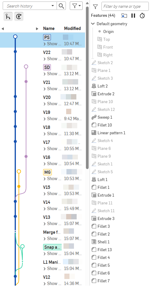
Traditional CAD tools are built around parametric, feature-based modeling. They excel at defining precise, functional geometry using sketches, extrusions, shells, and patterns — ideal for mechanical parts with well-defined tolerances and draft requirements. These systems rely on a "feature tree" that allows users to adjust dimensions and regenerate models in a predictable way.
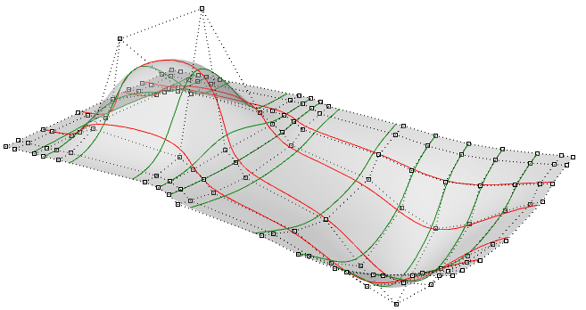
Rhino, by contrast, is a surface modeling tool that offers full freedom to sculpt complex, flowing forms. It’s based on NURBS (Non-Uniform Rational B-Splines), a mathematical framework that enables the creation of highly detailed and smooth surfaces. While this gives industrial designers and form-givers exceptional creative control, it also removes the structure and constraints that make feature-based CAD models so robust and editable.
The core challenges
1. Geometry without history
Rhino does not create parametric feature trees. Once a surface is built, its underlying logic isn’t preserved — there's no sketch, no extrusion, no reference. If you later need to adjust wall thickness, add ribs, or apply draft angles, these edits must be done manually and often destructively. In contrast, a parametric model allows such changes in seconds.
2. Continuity and surface quality
Smooth surface transitions are critical — especially in visible plastic parts. Rhino allows high-order continuity (G2, G3), which can result in beautiful transitions. But in feature-based CAD systems, surface continuity is typically limited to G1 (tangency). Maintaining curvature continuity across multiple surfaces can be nearly impossible once the model is imported.
3. Broken topology on import
When Rhino models are exported to STEP or IGES and imported into a CAD system, they often arrive as "dumb geometry" — just faces and edges, without solid definitions. These faces may have micro-gaps, overlaps, or tolerance mismatches. The result? Failed attempts at joining surfaces, shelling the part, or applying fillets.
4. Shelling and mould development failures
For plastic components, shelling is essential. It defines wall thickness and prepares the part for mold creation. But shell operations require a watertight, well-behaved solid. Freeform Rhino surfaces often fail at this step, especially if they have internal curvature conflicts or open edges. Creating a parting line or core/cavity split becomes a manual — and error-prone — process.
5. Assembly and fit issues
Plastic parts rarely exist in isolation — they’re assembled, snapped together, or fastened to other components. Rhino surfaces, when not perfectly aligned or toleranced, can create issues in downstream assemblies. Even a fraction of a millimeter can lead to interference or misfit when transferred into a solid CAD assembly.

We embrace designers because they do things we can't, but sometimes they don't realize how much their ignorance can be a pain in the ass process.
A practical example: Ergonomic plastics
Take a handheld product like a remote control. The industrial designer models a beautiful, ergonomic shell in Rhino, perfectly sculpted to the user’s grip. But the mechanical engineer struggles to convert that form into something manufacturable. The shell fails due to open surfaces. Draft analysis is meaningless because curvature varies too unpredictably. Shell thickness can’t be applied. Ribs and bosses have no reference faces. Ultimately, the engineer may need to recreate the surfaces manually — losing time and risking deviations from the original design intent.
Conclusion
Rhino is a powerful tool for creating complex, freeform surfaces. But the freedom it offers comes at a cost: reduced compatibility with solid CAD environments and increased effort in preparing models for production. To bridge the gap between design and manufacturing, early collaboration between industrial designers and mechanical engineers is essential. Surface strategies must be defined early, tolerances controlled, and geometry carefully prepared before it reaches the mouldmaker stage.
Rhino surfaces can be used in production — but only with deep surface modeling expertise and close control over geometry quality. Otherwise, what starts as a beautiful form may become a barrier to manufacturability.
© 2017 - Present, BÖHME ApS. All Rights Reserved.